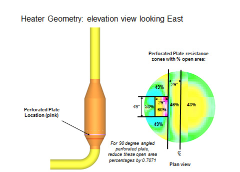
This report outlines the thermal analysis and airflow distribution model as part of an air heater package produced by Zeeco. The first section includes design details of the flow distribution grid applied in the inlet of the heater, located below the duct burners. The grid design was based on a CFD analysis.
The second section includes an analysis performed by Zeeco to determine the final temperature distribution at the exit of the heater. This was accomplished using a program to perform a thermal balance based on flow and temperature on each element. These elements are created by cutting the heater into a number of cross sections at different elevations and overlaying a grid on each section.
Thermal Analysis
The objective of the thermal analysis was to determine the final temperature distribution at a cross section located at the outlet of the air heater and controlled heat release (drilling pattern. This ensures that the temperature variance was minimized to meet the specification. Calculations were performed by dividing each cross section into 6”x6” square elements in a grid pattern. This determined the temperatures performed for each element at cross sections every 6” in elevation above the burners, starting at the level of fuel injection. The provided drilling was used to find the heat released at each cell. Calculations were performed until a satisfactory temperature variance was indicated or the top of the heater was reached. The temperature calculations process included taking three iterations at each cross section before the final temperatures were recorded.
结果
After the thermal analysis and airflow distribution model results have been reviewed, the heater temperature distribution is reported is sufficiently uniform (less than 1% variance from average) when the heater begins to neck down at the outlet. This result is due to the increased air mixing and time to reach equilibrium.
The following charts take the temperatures along several chords parallel to the North-South line of symmetry at several elevations. The elevations chosen are all at 12” apart so that all charts utilize the same formula for the 3rd Iteration. Z=264” is the final elevation shown, just below the point where the heater begins to neck down at the outlet.
下载技术文件